Demystifying the LTE Physical Downlink Control Channels
Note to the reader:
Abstract
The cellular networks of world are expected to top over 60 Exabytes of traffic every month by 2025 (Ericsson, n.d.). This is an astronomical amount of data and is the result of the engineering done in the 3GPP specification; especially as they formalize the 5G specification. This spec while telling a user whats going on is very minimal on why and lacks the digestibility and hook in points for new engineers. To understand the cellular network is impossible however understanding the physical channels/protocols on which the LTE networks are built provides a lot of insight in the 5G NR technology. The reason we need to understand 4G technology is because 5G can interoperate with LTE to provide all of the benefits with out the cost of new deploy all new UEs. The current 5G New Radio (NR) standard is in a non-standalone mode that uses the 4G LTE control plane as its foundation, however extends the control plane in bands out of reach to LTE. Thus understanding 5G requires investigating, explaining, and understanding the purpose and function of the existing physical level protocols such as PSS, SSS, PHICH, PFICH, PBCH, PDCCH PDSCH (Rinaldi, Raschellà, and Pizzi 2021). These protocols solve many of the major issues behind Synchronization, Multiplexing, error correction, and base line performance. And they are required to be understood before the UE can learn whether or not it can transmit in a cell. In this paper we will breakdown the physical downlink part of LTE. In doing so we will give a mix have high level and some of the Detail required for a UE to join the uplink.
Physical Layer Raw Radio Frame
Time Domain
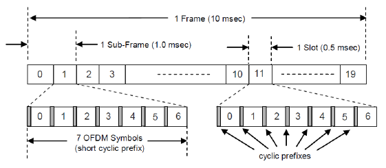
LTE allows for FDD (frequency division duplex) and TDD (Time division duplex) (3GPP 2017a) . The LTE spec goes to great length to have no difference architecturally between FDD and TDD and leaving only minimal difference in the MAC and higher level protocols related to TDD. In order to understand how physical protocols are going to encode data we need to understand what a Radio frame at its foundation. A single radio frame in LTE is 10ms long, regardless of whether or not TDD or FDD is used. (3GPP 2017a) We divide a radio frame further into a subframes which last 1 ms and slots which are 0.5 ms or half a subframe. We can further divide slots into 7 smaller blocks called symbols. One symbol here represents the time span of one point in a IQ constellation. See [RadioFrame] for a visual.
A Symbol has two parts in it: a CP (Cyclic Prefix) and a real data portion. The CP can be normal or extended. If the CP is extended it is longer and only 6 symbol will exist in that slot; since the timing of slots, subframes and frames are always fixed. (Ignoring this for simplicity) Each symbol in a slot (for downlink) is a OFDM (orthogonal Frequency Division Modulation) symbol and includes the CP and data. Symbols are modulated into the carrier channel format (BPSK, QPSK, 64QAM etc. etc.) and that data is transformed into the frequency domain via an FFT. The data portion is 2048 samples, while all but the first CP is 144 samples. The first CP is 160. The network takes these samples and runs a FFT to capture the symbol meaning and than runs a IFFT to modulate the data back out onto a subcarrier frequency (15KHz per a subcarrier) this transmission is assigned too and therefore symbol was mapped too. This resulting OFDM symbol is than ready to be transmitted (KeysightInc, n.d.). [SlotSymbolBreakdown] has a breakdown of the slot visual.
Now there is one important thing we are missing before we exit the discussion on raw frames. First OFDM is not typically used in uplink for UEs. (3GPP 2017a). This is because it has a high Peak to Average Power Ratios due to symbols potentially having constructive contributions to the overall power. (Orovic et al. 2011) This would kill battery life on UEs. Rather for uplink UEs use SC-FDMA, alternatively know as linear precoded OFDMA. This adds a DFT in encoding and decoding and in practice reduces power consumption. This symbol encoding is the same except there is a single carrier that all data is multiplex onto via a the DFT which is inverted at the receiver side. This is done because the UE does not need nor want the full power of OFDM because its not talking to other UEs its talking to one network, whereas the network needs the power that OFDM provides because its talking to many UEs and that expressability is key.
[RadioFrame]  (Ekuryu, n.d.)
[SlotSymbolBreakdown]  (Ekuryu, n.d.)
Resource Allocation
Above we talked about the raw Radio frame format, however, its important to under that the frame describes the time dimension of the underlying signals. There is is still the frequency domain to contend with and this requires thinking about bandwidth allocations. The smallest resource allocation available in LTE is the RB (Resource Block). An RB is 12 subcarriers (15KHz each) by 7 symbols (KeysightInc, n.d.). In the frequency spectrum this means a RB is 180 kHz wide and 1 slot long in time. Now one can reduce a RB to a smaller division a RE (resource element) which is 1 sub carrier by symbol. A RE is the smallest unit of data in LTE. The combined view of all RBs in a given spectrum allocation of LTE is called the Radio Resource Grid. There is a FDD reference grid in the appendix to make the idea of allocating channels clear.
LTE suppers many different bandwidths for both uplink and each is allocated a certain number of blocks the some examples are 1.4 MHz, 3 MHz, 20MHz. Each requires 6, 15, 100 RBs respectively. Now the important question becomes how does the network handle FDD and TDD. In a FDD frames the uplink and downlink portions are separated by frequency. This allows for Full Duplex in which both uplink and downlink frames are transmitted synchronously and continuously.
Now in the case of TDD resources are not split to different frequency rather there is switching that happens based on the network configuration and allocated resources. LTE supports 7 different TDD uplink/downlink distributions which allows the network to distribute transmission times better. The basics to these modes is that there is always a sync symbol transmitted by the network in TDD and than each configuration either uses 1 or 2 sync symbols. The possible configuration points are shown in [TDDSwitchingPoints] but at a high level as the network partitions slots based on the networks requirements for more uplink or downlink. There is always a downlink slot before a sync pulse and as the network requires more uplink bandwidth it adds more uplink slots and second sync slot. This leads to the network providing up to 60% of its available bandwidth to uplink.
Now to talk more about the Sync slots those are really made up a special slot that contains a downlink Sync pulse and a uplink Sync pulse since really but the network and the UEs have to synchronize with each other. These slots contain a DwPTS (downlink pilot time slot), followed by a GP (guard period) and than the UpPTS (uplink pilot time slot) (Ekuryu, n.d.). The most important thing to see is that that slots 0 and 5 are always reserved for downlink. This prevents the network from locking itself out even if there is a uplink transmitter who missed a change in configuration they will not block there only time to hear the network configurations.
[TDDSwitchingPoints]  (Ekuryu, n.d.)
Synchronization to the network
Synchronization
Now that we’ve established a basic radio frame that next big issue to deal with for efficiency radio communications is synchronization. There are two actors at play here in LTE here the UE(User Equipment) and the eNB (eNodeB). A UE is a cell phone or device that wants to attach to the network. The eNB is a interface placed in front of the network. In high level protocols the UE is really talking to the base station (network) through a eNB, however the eNB becomes transparent. We only talk about it here because the eNB coordinates the physical communications in the network (Ahmadi 2014). It can be thought of as a router to the web. LTE requires synchronization to the radio frame because its a 10ms periodic event driven message. If you are not synchronized you will read only noise or if your transmitting cause interference. There are two signals involved in LTE for synchronization in the DL direction i.e eNB \(\xrightarrow{}\) UE: PSS (Primary Synchronization Signal) and SSS (Secondary Synchronization Signal). The overall product of these two signals is to generate the \(N^{CELL}_{ID} = 3N^{(1)}_{ID} + N^{(2)}_{ID}\) which is the physical cell identity. In gain this value the UE acquire slot and than frame synchronization. There are 504 different values for the PCI (physical cell identity).
PSS
PSS is the first synchronization signal and provide slot synchronization in the DL (Downlink) direction. PSS is a based on a the frequency domain of Zadoff-Chu sequences and is used to determine the the cell identity group \(N^{(1)}_{ID}\) (Matlab, n.d.). The Zadoff-Chu sequence is a polyphase code with good periodic correlation originally made by Frank and Zadoff, Chu later showed that you could extend the construct for any code length (Chu 1972). What makes this sequence useful is having a zero cyclic auto-correlation at nonzero lags points (Chu 1972) (Matlab, n.d.). That means that when you compare this signal to a transposed version of itself there will be no matching. This coding helps to eliminate cross-correlation of simultaneous eNB transmitting thus reduce inter cell interface but also allows for a constant amplitude output signal reducing the cost and complexity of radio power amplifiers. Thinking about this from a complex-valued math perspective if you have two Zadoff-Chu sequences \(Z_1, Z_2\) where \(Z_2\) lags behind \(Z_1\). And apply them to another signal F you’d find that your correlation would be zero as follows \(Corr(Z_1 * F, Z_2 * F) = 0\).
Now that we know the what makes PSS useful lets talk about how its generated. The sequence \(d_u(n)\) 62 complex symbols long used for PSS is generated based on the following equations (Matlab, n.d.) \[\begin{gathered}
d_{\mu}(n) = e^{-j * \frac{\pi\mu n(n+1)}{63}} , \text{for n} = 0,1,...,30\\
d_{\mu}(n) = e^{-j * \frac{\pi\mu n(n+1)(n+2)}{63}} , \text{for n} = 31,32,...61\\\end{gathered}\] The \(\mu\) from above is the Zadoff Chu root sequence index and where n is steps in the frequency domain. (Paliwal, n.d.) This implicitly reveals part of the cell identity if one was to take a IDFT and correlate on the Zadoff Chu sequence. (Paliwal, n.d.) It takes 72 samples to transmit the PSS which is mapped to the 6 central RBs in the Grid. However, only 62 sub carriers centered on DC (the middle of the Grid) are used and both sides have a padding of 5 subcarriers. If the network is using FDD PSS is the last OFDM symbols in slots 0 and 10. And if the network is using TDD PSS maps to the 3rd symbols in slots 1 and 6. Remember these used to send the \(N^{(2)}_{ID}\) portion of cell identity.
SSS
Next is SSS is a pseudo-random binary sequence, that is created by cycling through a linear shift register of length m which results in a sequence of \(2^m-1\).(Matlab, n.d.) Three of these m sequences each of length 31 are used to generate the synchronization signals s,c and z which make up SSS. The sequences \(s_0^{m_0}\) and \(s_0^{m_1}\) are different cyclic shifts of the m sequence s. The indices \(m_0\) and \(m_1\) are based on the cell identity that the SSS \(N_{ID}^{(2)}\). (3GPP 2017b). The two sequences are scrambled using the binary scrambling code \((C_0(n), c_1(n))\) which depend on \(N^{(2)}_{ID}\).
Combine the signals s,c,z are generated by the following primitive polynomials in Galois Field 2. Here primitive means they are Irreducible and i.e prime polynomials. \[\begin{gathered}
s(x) = x^5+x^2+1\\
c(x) = x^5+x^3+1\\
z(x) = x^5+x^4+x^2+x+1\end{gathered}\] These generators are used to define fine the sub-index signals that will get transmitted as follows. \[\begin{gathered}
s_0(n) = s (n+m_0 \ (\mathrm{mod}\ 31))\\
s_1(n) = s (n+m_1 \ (\mathrm{mod}\ 31))\\
c_0(n) = c (n+N^{(2)}_{ID} \ (\mathrm{mod}\ 31))\\
c_1(n) = c (n+N^{(2)}_{ID}+3 \ (\mathrm{mod}\ 31))\\
z_0(n) = z (n+(m_0\ (\mathrm{mod}\ 8)) \ (\mathrm{mod}\ 31))\\
z_1(n) = z (n+(m_1\ (\mathrm{mod}\ 8)) \ (\mathrm{mod}\ 31))\\\end{gathered}\] Mapping the resulting scrambled sequences to alternating between the first and second SSS transmission in each radio frame allows the receiver to gain synchronization by receiving either subframe 0 or subfram 5 of the next frame. This halves the time the UE will lose synchronization with the network since there is a unique number to occur in each slot. In a FDD network: the SSS is transmitted one OFDM symbol before PSS in the middle 72 subcarriers of PSS. If the network is a TDD the SSS is mapped to the last OFDM symbol in slots 1 and 11 which is 3 before the PSS signal. In both FDD and TDD the SSS is scrambled differently for even and odd resource blocks which tells the UE more information. If in an even resource block. subframe 0: d(2n) = \(s^{(m_0)}_0(n)c_0(n)\). And for subframe 5: d(2n) = \(s^{(m_1)}_1(n)c_0(n)\) But if in a Odd resource block subframe 0: \(d(2n+1) = s^{(m_1)}_1(n)c_1(n)z_1^{m_0}(n)\) but if subframe 5: \(d(2n+1) = s^{(m_0)}_0(n)c_1(n)z_1^{m_1}(n)\). (Matlab, n.d.)
Pulling Synchronization together
After examining how the signals are generated its important to understand what the math is telling us. Primarily regardless of network type FDD/TDD each cell is transmitting one of 168 unique sequences in the SSS channel (each bit sequence is 62 bits long). And one of three unique sequences (62 bit Zaddoff-Chu sequences). The tuple joins together to create one of 504 unique physical cell ID. This Physical cell id is what describes scrambling else where in the LTE signal and ensures network UE synchronization.
Locking onto PSS and SSS
Now while we have described what PSS and SSS look like and what they are used for we still need a way to detect them. A rudimentary but fool proof way detecting these signals is by correlation. Since the signals are periodic and well described math mathematically one can simply generate a PSS signal it takes only 3 possible states and cross correlate it from the received IQ stream. High correlation means you have both synchronized and discovered the the PSS root index. Next is discovering your SSS parameters, however guess and check is not so good here because there are over a 100 options. Rather remember since you have generated PSS and correlated it the networks PSS you know have slot timing and a basic resource grid. PSS is center at DC which means that you have an even odd indexing of resource block and know where subframe 0 and subframe 5 are. Furthermore we know the \(N_{ID}^{(2)}\), now we can follow an algorithm outlined by Kim Jung whose block diagram is shown below (Kim, n.d.)[sssalgo] Essentially we can use the given facts to solve for the \(c_0(n)\) parameter since we have values (by sampling aided by timing recovery of PSS) for d(n) for all n we can use the series of equations to solve for each component of SSS. First we start with even frames since they isolate \(c_0(n)\) and than \(c_1(n)\). These isolated values are than used in either direct correlation or differential correlation to solve for the \(m_0,m_1\) pair which builds the cell identity. This differential implementation in more detail can be found by the srsRAN project’s github linked below in particular look for the srsran_sss_m0m1_diff_coh() function in srsRAN/lib/src/phy/sync/find_sss.c file. (Srsran, n.d.)
[sssalgo]  (Kim, n.d.)
Scrambling in LTE [scrambling]
A major product of PSS and SSS is the PCI (Primary Cell Identity), which is used as an input to scramble many channels that a UE is going to read/connect too. The specific scrambling algorithm used is know as Gold Sequences. This scrambler is defined by the following polynomial generator formula c which relies on initialization polynomials \(x_1, x_2\) which are channel specific but entangle the PCI into there initialization. Finally a Shift amount \(N_c\) which included via spec is also channel specific. (3GPP 2017b) I will show the general sequence but for simplicity ignore the channel specific initialization as there are quite a few and using the 3GPP spec is important to learning how to understand the LTE radio stack. The sequence c(n) is the resulting scrambling sequence you XOR into you message to scramble it. \[\begin{gathered} c(n) = (x_1(n+N_c) + x_2(n+N_c)) \ (\mathrm{mod}\ 2)\\ x_1(n+31) = (x_1(n+3) + x_1(n)) \ (\mathrm{mod}\ 2)\\ x_2(n+31) = (x_2(n+3) + x_2(n+1) + x_2(n+2) + x_2(n)) \ (\mathrm{mod}\ 2)\end{gathered}\]
For those interested in an implementation I once again recommend srsRAN’project github look for srsRAN/lib/src/phy/scrambiling/scrambling.c (Srsran, n.d.). If one is trying to do this in hardware a parallel Linear Feedback Shift Register is recommended to avoid data propagation delays when scrambling since it is such a common function required.
Mining the MIB
High level
After a UE has achieved synchronization and read the PCI it needs to read the Master Information Block (MIB) and System Information Blocks (SIBs). These two data structures are broadcasted regularly by the network’s eNB cells. The MIB contains information about cell bandwidth, information on the Physical HARQ Indicator Channel (PHICH), and the System Frame Number (SFN). The SIBs are transmitted on the Downlink Shared Channel (DL-SCH) which is mapped onto the Physical Downlink Shared channel PDSCH. (Matlab, n.d.).
MIB contents
Before the UE does MIB decoding it does not know the full system bandwidth even though it has synchronized. Furthermore, the UE has not established the band plan. Thus the UE relies on the spec, which says the MIB lays in the central 72 subcarriers i.e 6 resource blocks. to account for this. Inside this the MIB contains 24 bits for information. 3 bits for the system bandwidth, 3 bits for PHICH 1 bit for CP and 2 for PHICH Ng value. It also has 8 bits for System Frame Number SFN and 10 reserved bits. An updated MIB is transmitted every 4 frames however the last MIB in used is transmitted every radio frame so that a UE can always join the network.
When decoding the MIB, which is 24 bits is entangled with a a corresponding CRC16_CCITT_ZERO for a total of 40 bits. However, the 3GPP spec plays a fancy trick of masking (XORing) the CRC with 0x0000, 0x5555, or 0xffff to encode whether the eNB has 1,2, or 4 antenna ports for encoding purposes, also known as MMIO. (3GPP 2022). These 40 bits are then sent through a convolution encoder whose encoding matrix is shown below visually. The matrix is has 7 delay slots and is a \(\frac{1}{3}\) encoder. The three streams from the encoding are than accumulated as all 120 bits stream whose than replicated 16 times for a total of 1920 bits. The resulting sequence is than scrambled using the the PCI and finally the overall sequence is send by the eNB using QPSK (reduces down to 960 complex symbosls) and centers the signal in the 6 central resource blocks, slot 2, symbols 0,1,2, and 3 of the radio frame. This is part of the spectrum is always dedicated to the PBCH or physical broadcast channel. (Matlab, n.d.).

(3GPP 2022)
Decoding the MIB in PBCH
Decodiing the MIB is straigh forward process. The UE simply needs to demodulate the signal area with QPSK. With each symbol the correct Gold sequence is applied. Than Viterbi’s algorithm is applied to reverse the Convolution coder. Note that convolution encoding step is use in almost every signal transmission so a robust hardware decoder is recommend for speed and power concerns (Adiono, Ramdani, and Putra 2018). Finally, the signal’s CRC check can be removed and checked against the input MIB, with caution around the antenna diversity mask.
Important takeaways for the MIB
Now a curious read might ask why so is dedicated to PBCH when it is transmitting the MIB after all it has 16x by 3x redundancy and is transmitted every radio frame even though its only updated every 4th frame. This equals a 192 Kbps DL bandwidth overhead just for the MIB! The reason is simple if the UE has not decoded the MIB they do not know the system bandwidth, MMIO antenna configuration, the SFN, or coefficients required to decode the PHICH (physical HybridARQ Indicator channel) or PDCCH (Physical Downlink Control Channel) (3GPP 2022). Decoding the PDCCH space is difficult because it is mapped in the same space as PHICH and PFICH and is essential the 1-4 OFDM symbols of the first slot in every subframe. This everything except PHICH and PFICH makes it the trickiest DL control channel to demodulate. But it is also the work horse of UL/DL allocations and while the UE has not decoded the MIB its essentially off limits.(Destevez 2022)
Decoding Physical Channels and UE’s next steps
After the UE has decoded MIB a lot of channels are be tractable to decode. The UE’s most likely goals include decoding the SIB (System Information Blocks), attempting the RACH (Random Access Channel) process to attach tp the the network high level protocols via RRC, NAS, and EPS (Evolved Packet System). There are an incredible number of services the UE can request from the network more than are possible to go over in any detail. In order present the best information density we are going to focus the remain of the paper on decoding several lower layer channels while avoiding going into extreme detail of the higher level services. The high level services make up 10000s of pages in the 3GPP spec, and will quickly overwhelm readers where as the lower level channels make up maybe 1000-5000 pages. The major objective following this point is give a reader starting points to access the feature rich environment of LTE’s more low level services. The extended goal is also productive as LTE and NR (5G) are interoperable in many regards. One channel in LTE most likely exists and is still required in NR with some modifications and improvements to the reserved data sections that were built into LTE. (Destevez 2022)
PCFICH - Physical Control Frame Indicator Channel
Purpose and Organization
PCFICH whole purpose is to transmit the CFI or control format indicator. The CFI can be 1,2,3 and has special code word for each value. The CFI informs the UE how many OFDM symbols are mapped for PDCCH. The PCFICH is mapped to the first OFDM symbol in each downlink subframe. The UE decodes this channel to allow decoding of the PDCCH. The PCFICH is always carried by 4 equally spaced REGs (resource element groups) (16 REs resource elements). The CFI location is \(\hat{z}=z(0),z(1),z(2),z(3)\). Where \[\begin{gathered}
z(0) = \hat{k} = \frac{N_{SC}^{RB}}{2} * N^{cell}_{ID} \ (\mathrm{mod}\ 2N^{DL}_{RB}) \\
z(1) = \hat{k} + \floor{\frac{N^{DL}_{RB}}{2}} * \frac{N_{SC}^{RB}}{2} \ (\mathrm{mod}\ N_{SC}^{RB} N^{DL}_{RB}) \\
z(2) = \hat{k} + \floor{\frac{2N^{DL}_{RB}}{2}} * \frac{N_{SC}^{RB}}{2} \ (\mathrm{mod}\ N_{SC}^{RB} N^{DL}_{RB}) \\
z(3) = \hat{k} + \floor{\frac{3N^{DL}_{RB}}{2}} * \frac{N_{SC}^{RB}}{2} \ (\mathrm{mod}\ N_{SC}^{RB} N^{DL}_{RB}) \end{gathered}\] Each z(i) value is the RE in which the next 4 elements are mapped to the part of CFI code word. Here \(N^{DL}_{RB}\) is the number of radio blocks for the given bandwidth. \(N^{RB}_{SC}\) is the number of subcarriers per radio block.
Encoding decoding
The whole process than looks as follows: The CFI is translated to the code word. The code word is than scrambled with the Gold sequence ([scrambling]). The scrambled sequence is than QPSK modulated and the mapped to resource elements as described above. (3GPP 2017b). Note I am ignoring the MMIO encoding step for simplicity. The decode step is very easily done in reverse since the groups are all fixed thus the mapping is predictable after you have decoded a MIB. The purpose of the simple QPSK modulation is that the Control side of the the Physical downlink channels reliability is more important than speed. Because, the majority of interesting data will be in the data plane side. Thus QPSK makes sense.
PHICH - Physical HybridARQ Indicator Channel
Purpose and Organization
PHICH is used to send Hybrid ARQ data to UEs. I.e ACKs and NACKs. This downlink channel is dedicated to supporting UEs who are using the PUSCH (Physical Uplink Shared Channel) and PICCH (Physical Uplink Control Channel)(Ekuryu, n.d.). When the network receives a message from the UE will generate an ACK in this channel the reason we are concerned with it early is that it takes up space in the Physical Downlink Control plane and we need to know about it to avoid it when decoding the PDCCH. A PHICH is used as an interchangeable name for the ARQ context will make it clear when we talk about sending a PHICH that’s an ARQ but if we talk about PHICH in general that’s about the actual channel settings. Now One PHICH is carried by multiple REGs and multiple PHICH can be carried by the same set of REGs and these multiple PHICH are called a PHICH group. A PHICH group will be multiplex with orthogonal codes. (Ekuryu, n.d.).
Multiplexing explained
A PHICH ARQ is identified by an index pair \((n^{group}_{PHICH}, n^{seq}_{PHICH})\) where \(n^{group}_{PHICH}\) is the group number and \(n^{seq}_{PHICH}\) is the sequence number. (3GPP 2017b). If the network is FDD than the number of PHICH groups is constant and given by \[N^{group}_{PHICH}
\begin{cases}
\ceil{N_g \frac{(N^{DL}_{RB}}{8})} & \text{Normal CP} \\
\{2*N_g \frac{(N^{DL}_{RB}}{8}) & \text{Extended CP}
\end{cases}\] where \(N_g = \{\frac{1}{6}, \frac{1}{2}, 1, 2\}\) and given by the MIB. However if TDD is in use you must reference the 3GPP spec’s distribution table. There is not a excellent formula to describe it you just have to know what the uplink configuration is and the current subframe number. This table is actually nice however because it allows a UE to safe power by ignore this channel when it has no transmissions. Regardless of network type up to 8 PHICH can be in a group (4 if extend CP is used).
The frequency mapping of PHICH depends on a term known as \(n_0\) which is the the number of the REGs in the first symbol of the subframe which are not used by PCFICH. Typically in FDD this will be \(2N^{DL}_{RB} - 4\). After this all REGs are numbered from 0 to \(n_0-1\) in order of increasing frequency. The 3 REGs used by PHICH group m are place according to this formula \((N^{ID}_{CELL} + m + \floor{\frac{j*n_0}{3}}) \ (\mathrm{mod}\ n_0)\) for j = 0,1,2. This leads to an even distribution of REGs. Now the formula technically changes for extend CP however we will be ignoring this for brevity.
Encoding and decoding
Now the encoding format used for PHICH is very simple first the channel is coded by translating ACK and NEGS to there respective format than the resulting symbols are BPSK modulated and than multiplied by the orthogonal sequence defined by 3GPP 36.211 table 6.9.1-2 (3GPP 2017b). Finally those symbols are mapped as shown above.
PDCCH - Physical Downlink Control Channel
High level
PDCCH is used to convey control data for uplink grants and scheduling the PDSCH (Physical Downlink Shared Channel). In general the PDCCH carries all control information not carried by PBCH, PCFICH, and PHICH. This constructive format of channels will become quickly apparent because to perform high level network operations a UE has to navigate the web of channels. This web of channels is useful from the eNB and networks perspective because they are designed to service a large number of UEs efficiency. It also allows the network to manage traffic at much higher level.
Encoding details
Both PBCH and PDDCH use a tail biting encoding where k=7, and r = \(\frac{1}{3}\) convolution code and circular buffers for rate matching along with QPSK. This design is optimized for performing punctual repetition codes to achieve the require codeword sizes(Destevez 2022). Similarities end there though. The PDCCH uses Downlink Control Indicators or DCIs to convey the control messages and there are many formats. Its uses the resource element groups (REGs) that are not allocated to PCFICH and PHIICH. A REG is defined as a set of 4 resource elements which are adjacent in frequency if you ignore the resource elements used by the CRS (Cell specific reference signal). The control region is the first 1,2, 3 or 4 symbols of subframe and its size is given by CFIs (Control Format Indicator). The CFI is carried in the PCFICH. Each subframe can have several DCIs depending on the size of the control region however PDCCH may use all its allocated REGs or leave some empty. PDCCH uses the concept of CCEs (control channel elements) to define how many resource elements are allocated. a CCE is a set of 9 REGs, and so a CCE contains 36 resource elements and since PDCCH uses QPSK, it carries 72 bits. (Destevez 2022).
The pieces of information of interest in this channel are the DCIs and they will be encoded to be 1,2,4, or 8 CCEs long which equals 72, 144, 288, or 576 bits respectfully. This is known as the aggregation level (Ekuryu, n.d.). These code words distributions and be seen in a figure blow provided by (Ahmadi 2014). As with the MIB in PBCH, DCIs include a 16-bit CRC which is also masked with RNTI (radio network temporal identifier) assigned by the network to a UE after a RACH procedure. And just like the MIB the RNTI conveys extra information to but in this case instead of a MMIO configuration its is used to address a DCI to a specific UE since the RNTI is unique per UE group. I say group because there are special RNTIs like the P-RNTI or paging RNTI (0xfffe) and the SI-RNTI or system information RNTI (0xffff). When decoding DCIs a UE has to remember to XOR this CRC mask out to confirm the message is meant for them. Thus only Paging and System DCIs (SIBs) are decodable before the UE connects to the network. There is also some MMIO port masks that can be added. however this is beyond this paper.
Now to tie this together mathematically to make the process of channel coding clear. Say you have an array of DCIs called A whose formats have/will be transmitted as CFIs in the PFICH. Than \(\forall \hat{a_i} \in A\) let \(\hat{c_i} = \hat{a_i} \| \text{CRC}(\hat{a_i})\) s.t \(\hat{c_i} = c_{0,i} ... c_{K-1,i}\) where K \(=\| \hat{a_i} \| -1\). If the given DCI is RNTI specific than you must xor \(X_{rnti} = x_{rnti,0} + x_{rnti,1} + ... + x_{rnti,15}\) into the CRC. Finally the product now undergoes channel coding via tail bit convolutional coding with a coding rate of \(\frac{1}{3}\) to produce \(\hat{b_i} = \text{conv}_{\frac{1}{3}}(\hat{c}_i)\). Now each of the \(\hat{b_i}\) are multiplex into a long stream interleaving each bit of every DCI next to each other i.e it groups the 0th digits, 1st digits, 2nd digits, ... of all the DCIs. This is a type of permutation and it looks like for \(\hat{b_i} = b_0^{(i)} + b_1^{(i)} + ... + b_{\| \hat{b_i}\| -1}^{(i)}\) where i indicates a new DCI. All these symbols are than concatenated to \(\hat{m} = b_0^{(0)} + b_0^{(1)} + ... + b_{\|\hat{b_0}\|-1}^{()} + b_{\|\hat{b_1}\|-1}^{(1)}\)
Decoding
Now decoding this channel requires you to know the frequency mapping of REGs from PHICH and PFICH. Along with the CFI number. Essential all REs not in those groups (or the reference signal). Are available to PDCCH. Taking theses REs the UE must first demodulate the QPSK signal, than remove the gold sequence scramble. Next the UE must undo the multiplexed the DCIs and undo the rate matching leaving only the RAW DCIs + CRC. To verify that any given DCI is for the the UE, the UE must look for the RNTIs of interest this is the C/SI/P RNTIs as given above and if that RNTI XOR out of CRC allows the CRC to match the UE than knows that DCI is meant for it. (Ekuryu, n.d.).
PDSCH - Physical Downlink Shared Channel
Overview of DCIs
Now that the UE can decode all of the Physical control channels and learn about DCIs. DCI have countless formats and sizes and all mean different things. Writing out all of those mappings likely will not be useful. What is useful is to understand that any DCI is mapping from PDCCH to PDSCH to tell the UE what is being transmitted next. It is like the grand central staging terminal and must be read before boarding any train. Thus to DCIs can be understood as contain 2 basic things: UL resource allocation and descriptors about DL data transmitted to the UE. (Ekuryu, n.d.)
DCIs common parameters
There are a lot of formats for DCIs but they have many commonalities. DCIs can contain a MCS or modulating coding schema to tell what type of modulation to use. This grants flexibility and can increase bandwidth utilization. DCIs also usually have RIVs or Resource Indication Value, which are responsible for telling the UE which PRB it should use. (Ekuryu, n.d.) NDI - new data indicator, TPC - Transmit Power Control, HARQ, and Redundancy versions. There are many types but in general they provide everything the UE needs to know what the network is sending and when in the frequency domain.
SIBs
The UE has a keen interest one set of DCIs in particular and that are SIB DCI that are entangled with SI-RNTI. in order to transmit and attach to the network the UE needs to read the first 2 SIBs however the UE will likely be interested in at least the first 5 SIBs for efficiency reasons. SIB 1 contains the scheduling of other SIBs along with access board stroke Cell barring access permissions. (Sqimway, n.d.). SIB 2 contains information about UL frequency and bandwidth, ac-barring and ssac-barring lists. Both of the barring lists have well define formats in the 3GPP spec (Ekuryu, n.d.). SIB 3,4,5 all contain information related Cell Re-selection and black lists, however, these are less important than the first 2 for getting a UL grant. (Sqimway, n.d.).
Closing thoughts and LTE limitations
The process of writing this paper was very intense as the 3GPP LTE spec is massive even when restricted to Physical Channels in the downlink only . However, from a standardization perspective LTE is excellent and layers well, unlike some of the previous methods for Cellular organization LTE has a very distinct layers similar to the networking OSI model. This makes it much more digestible and also reveals a lot of what the network traffic would look like and how one could experiment with reading data off the network. In particular I think some key insights in communication that LTE does is defining a fairly robust resource grid and radio frame, in fact this carries over to 5G NR networks, however the definition is refined to allow slots to have variable length. This was a key limitation in LTE because it prevents people from increasing signal speed just bandwidth speed via more PRBs. Furthermore, when LTE came out it was an entirely new network this made the transition very costly and this is why NR has adopted a more transparent transition where NR can inter operate with LTE to make the NR adoption easier to roll out. While these might seem like minor things they are very important for the adoption of a new standard.
Appendix - Radio Resource Grid
Parameters used to generate: Bandwidth = 1.4 MHz, CFI = 1, FDD, Normal CP. Normal PHICH duration with PHICH Ng = 1.
Citations
3GPP. 2017a. “Evolved Universal Terrestrial Radio Access (E-UTRA); Radio Resource Control (RRC); Protocol specification.” Technical Specification (TS) 36.331. 3rd Generation Partnership Project (3GPP). https://portal.3gpp.org/desktopmodules/Specifications/SpecificationDetails.aspx?specificationId=2440.
———. 2017b. “Evolved Universal Terrestrial Radio Access (E-UTRA); Radio Resource Control (RRC); Protocol specification.” Technical Specification (TS) 36.211. 3rd Generation Partnership Project (3GPP). https://www.etsi.org/deliver/etsi_ts/136200_136299/136211/14.02.00_60/ts_136211v140200p.pdf.
———. 2022. “Evolved Universal Terrestrial Radio Access (E-UTRA); Radio Resource Control (RRC); Protocol specification.” Technical Specification (TS) 36.212. 3rd Generation Partnership Project (3GPP). https://www.etsi.org/deliver/etsi_ts/136200_136299/136212/17.01.00_60/ts_136212v170100p.pdf.
Adiono, Trio, Ahmad Zaky Ramdani, and Rachmad Vidya Putra. 2018. “Reversed-Trellis Tail-Biting Convolutional Code (Rt-Tbcc) Decoder Architecture Design for Lte.” International Journal of Electrical and Computer Engineering (IJECE) 8 (1): 198. https://doi.org/10.11591/ijece.v8i1.pp198-209.
Ahmadi, Sassan. 2014. LTE-Advanced a Practical Systems Approach to Understanding 3GPP Lte Releases 10 and 11 Radio Access Technologies. Elsevier Science.
Chu, D. 1972. “Polyphase Codes with Good Periodic Correlation Properties (Corresp.).” IEEE Transactions on Information Theory 18 (4): 531–32. https://doi.org/10.1109/TIT.1972.1054840.
Destevez, Daniel. 2022. “LTE Downlink: PBCH and Pdcch.” Daniel Estvez. https://destevez.net/2022/07/lte-downlink-pbch-and-pdcch/.
Ekuryu, J. A. n.d. “LTE Handbook.” ShareTechnote. https://www.sharetechnote.com/html/Handbook_LTE.html.
Ericsson. n.d. “Ericsson Report.” https://www.ericsson.com/en/reports-and-papers/mobility-report/reports/november-2021.
KeysightInc. n.d. “LTE Physical Layer Overview.” LTE Physical Layer Overview. https://rfmw.em.keysight.com/wireless/helpfiles/89600b/webhelp/subsystems/lte/content/lte_overview.htm.
Kim, Jung. n.d. “SSS Detection Method for Initial Cell Search in 3GPP ... - Sharetechnote.” https://www.sharetechnote.com/Docs/SSS_DetectionMethod_JungInKim.pdf.
Matlab. n.d. “Cell Search, Mib and Sib1 Recovery.” Cell Search, MIB and SIB1 Recovery - MATLAB &Amp; Simulink. https://www.mathworks.com/help/lte/ug/cell-search-mib-and-sib1-recovery.html?s_tid=srchtitle_LTE+Cell+Search_4.
———. n.d. “LtePSS.” Synchronization Signals (PSS and SSS) - MATLAB; Simulink. https://www.mathworks.com/help/lte/ug/synchronization-signals-pss-and-sss.html.
Orovic, Irena, Nikola Zaric, Srdjan Stankovic, Igor Radusinovic, and Zoran Veljovic. 2011. “Analysis of Power Consumption in Ofdm Systems.” In, 1:653–57.
Paliwal, Vikas. n.d. “Cell Search Procedures in Lte Systems - Carleton.” http://www.sce.carleton.ca/~vpaliwal/index_files/drm.pdf.
Rinaldi, Federica, Alessandro Raschellà, and Sara Pizzi. 2021. “5G Nr System Design: A Concise Survey of Key Features and Capabilities.” Wireless Networks 27 (8): 5173–88. https://doi.org/10.1007/s11276-021-02811-y.
Sqimway. n.d. “LTE Radio Resources.” LTE Radio. https://www.sqimway.com/store_lte.php.
Srsran, SRS. n.d. “Srsran/Srsran: Open Source Sdr 4G/5G Software Suite from Software Radio Systems (Srs).” GitHub. https://github.com/srsran/srsRAN/tree/master.